
All the informations present in this article are coming from the Boeing FCOM (Flight Crew Operations Manual). It contains AFM (Airplane Flight Manual) limitations, AFM operational information and non-AFM operational information.
Limitations and operational information marked with a “#” symbol need to be memorized.
Some values might be different from an operator to another. At least, it gives an idea.
Airplane General
Runway slope: +/- 2%
# Maximum Takeoff Component: 10 knots
# Maximum Landing Tailwind Component: 10 knots
15 knots (approved airfields only)
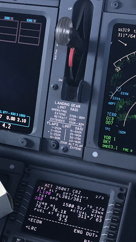
Maximum speeds: Observe gear and flap placards. (250 knots below FL100 unless approved by ATC and within class A, B or C)
Maximum Operating Altitude: 41,000 ft
Maximum Takeoff and Landing Altitude: 8,400 ft
Maximum flight operating latitude is dependent on the configuration of the Magnetic Variation tables in the ADIRU as follows: 82° North and 82° South, except for the region between 80° West and 170° West longitude, the maximum flight operating latitude is 73° North, and the region between 120° East and 160° East longitude, the maximum flight operating latitude is 60° South.
Installation of handle covers on the overwing exits must be verified prior departure whenever passengers are carried.
Verify that an operational check of the flight deck door access system has been accomplished according to approved procedures once each flight day.
# Severe Turbulent Air Penetration speed is 280 KIAS / .76M, whichever is lower.
Applicable to Climb and Descent only.
During cruise, set turbulence penetration N1 as highlighted by TURB N1 on the cruise page. Severe turbulence will cause large and often rapid variations in indicated airspeed. DO NOT CHASE THE AIRSPEED.
– FMC N1 LIMIT page – Select CON
– Yaw Damper – Engaged
– Autopilot – Optional – If the autopilot is engaged, use CWS position, do not use ALT HLD mode.
– Autothrottle – Disengage.
– Attitude – Maintain wings level and the desired pitch attitude. Use the attitude indicator as the primary instrument. In extreme drafts, large attitude changes may occur. DO NOT USE SUDDEN LARGE CONTROL INPUTS. After establishing the trim setting for penetration speed, DO NOT CHANGE STABILIZER TRIM.
– Altitude – Allow the altitude to vary. Large altitude variations are possible in severe turbulence. Sacrifice altitude in order to maintain the desired attitude and airspeed. DO NOT CHASE THE ALTITUDE.
– Thrust – Engine ignition should be on. Position the ENGINE START switches to FLT. Make an initial thrust setting for the target airspeed. CHANGE THRUST ONLY IN CASE OF EXTREME AIRSPEED VARIATION. The FMC cruise page displays N1 target value for turbulence.
Crosswind Limitations

Altitude Display Limits for RVSM Operations
Standby altimeters do not meet altimeter accuracy requirements of RVSM airspace.
The maximum allowable in-flight difference between Captain and First Officer altitude displays for RVSM operations is 200 feet.
The maximum allowable on-the-ground altitude display differences for RVSM operations are:
| Field Elevation | Max Difference Between Captain & F/O | Max Difference Between Captain or F/O & Field Elevation |
| Sea Level to 5,000 feet | 50 feet | 75 feet |
| 5,001 to 10,000 feet | 60 feet | 75 feet |
Weight Limitations
Maximum Taxi Weight: 78,217 Kilograms (or as per Aircraft Weight Certificate)
Maximum Takeoff Weight: 77,900 Kilograms (or as per Aircraft Weight Certificate)
Maximum Landing Weight: 65,317 Kilograms (or as per Aircraft Weight Certificate)
Maximum Zero Fuel Weight: 61,688 Kilograms (or as per Aircraft Weight Certificate)
Air Systems
Pressurization
The maximum cabin differential pressure (relief valves) is 9.1 PSI.
With either one or both engine bleed air switches ON, do not operate the air conditioning packs in HIGH for takeoff, approach or landing.
Note: The fire protection Non-Normal procedures take precedence over the statement regarding no air conditioning pack in HIGH during takeoff, approach, or landing. The CARGO FIRE and SMOKE/FUMES REMOVAL checklists require the Operating PACK switch(es) HIGH. Switch(es) need to be placed in HIGH in order to increase ventilation for smoke removal
Autopilot / Flight Director System
# Use of aileron trim with the autopilot engaged is prohibited.
# Do not engage the autopilot for takeoff below 400 feet AGL.
# Airplanes operating with EASA Certification: The Minimum Use Height (MUH) for single channel autopilot operation is defined as 158 feet AGL.
# Maximum allowable wind speeds, when conducting a dual channel Cat II or CAT III landing predicating on autoland operations, are:
- Headwind 25 knots
- Crosswind 20 knots
- Tailwind 10 knots
# Maximum and minimum glideslope angles for autoland are 3.25° and 2.5° respectively.
# Autoland capability may only be used with flaps 30 or 40 and both engines operative.
# Do not use LVL CHG on final approach below 1000 feet AFE.
Communications
Do not use VHF-3 (if installed for voice communication) for ATC communications with ACARS operational.
Use the VHF radio connected to the top of fuselage antenna for primary ATC communications on the ground.
Engines and APU
Engine Limit Display Markings
Maximum and minimum limits are red.
Caution limits are amber.
Engine ignition
Engine ignition must be on for:
- takeoff
- landing
- operation in heavy rain
- anti-ice operation
Thrust
Operation with assumed temperature reduced takeoff thrust is not permitted with anti-skid inoperative.
Reverse thrust
# Intentional selection of reverse thrust in flight is prohibited.
APU
# Airplanes operating with EASA Certification: APU bleed + electrical load: maximum altitude 10,000 feet.
# APU bleed: maximum altitude 17,000 feet
# APU electrical load: maximum altitude 41,000 feet.
APU bleed valve must be closed when:
- ground air connected and isolation valve open
- engine n°1 bleed valve open
- isolation and engine n°2 bleed valves open
APU bleed valve may be open during engine start, but avoid engine power above idle.
After three consecutive aborted start attempts, a fifteen minute cooling period is required.
Flight controls
# The maximum altitude with flaps extended is 20,000 feet.
# Holding in icing conditions with flaps extended is prohibited.
In flight, do not extend the SPEED BRAKE lever beyond the FLIGHT DETENT.
# Avoid rapid and large alternating control inputs, especially in combination with large changes in pitch, roll, or yaw (e.g. large side slip angles) as they may result in structural failure at any speed, including below VA.
Airplane operating wit EASA Certification: Flaps 15 normal landings are prohibited. A Flaps 15 landing may be performed when required by a non-normal procedure.
# Do not deploy the speed brakes in flight at radio altitudes less than 1,000 feet.
# With flaps 15 ot greater, the speedbrakes must be retracted.
Alternate flap duty cycle:
- When extending or retracting flaps with the ALTERNATE FLAPS position switch, allow 15 seconds after releasing the ALTERNATE FLAPS position switch before moving the switch again to avoid damage to the alternate flap motor clutch.
- After a complete extend/retract cycle, i.e., 0 to 15 and back to 0, allow 5 minutes cooling before attempting another extension.
Flight Management, Navigation
Air Data Inertial Reference Unit (ADIRU)
ADIRU alignment must not be attempted at latitudes greater than 78 degrees 15 minutes.
All flights operations based on magnetic heading or magnetic track angle are prohibited in geographic areas where the installed IRS Magnetic Variation table errors are greater than 5°.
Refer to AFM Normal Procedures/Inertial Reference System section for procedures to determine the geographic areas and magnitude of Magnetic Variation errors for the specific Magnetic Variation table installed in the IRS and if any of these limitations apply.
Look-ahead Terrain Alerting ( GPWS)
Do not use the terrain display for navigation.
Do not use the look-ahead terrain alerting and terrain display functions:
- within 15nm of takeoff, approach or landing at an airport not contained in the GPWS terrain database.
Runway Awareness and Advisory System (RAAS)
RAAS alerts shall not be used for navigational purposes.
RAAS visuals messages and status messages are only shown the Terrain Display. As such, Terrain Display must be selected on one of the Navigation Displays for these messages to be visible to the crew. RAAS aural alerts are not affected by selection of the Terrain Display.
Pilots may not use RAAS advisories as a replacement for NOTAM or Automatic Terminal Information Service (ATIS) information.
The RAAS system does not know the location of taxiway hold short lines and is not approved as a ground navigation aid.
The absence of RAAS alerts, in particular “Long Landing”, does not mean that the aircraft can be safely operated from or into the runway.
# Avoid weather radar operation in a hangar.
Avoid weather radar operation when personnel are within the area normally enclosed by the aircraft nose radome.
Note: The hangar recommendation does not apply to the weather radar test mode.
Fuel system
Maximum tank fuel temperature is 49°C.
Minimum tank fuel temperature prior to takeoff and inflight is -43°C, or 3°C above the fuel freezing point temperature, whichever is higher.
Note: The use of Fuel System Icing Inhibitor additives does not change the minimum fuel tank temperature limit.
Intentional dry running of a center tank fuel pump (low pressure light illuminated) is prohibited.
Fuel Balance
Lateral imbalance between main tanks 1 and 2 must be scheduled to be zero. Transient fuel imbalance must not exceed 453 kgs for taxi, takeoff, flight or landing.
Fuel Loading
Main tanks 1 and 2 must be full if center tank contains more than 453 kgs.
Landing Gear
Airplanes operating with EASA Certification: Towing operations without the use of a tow bar is restricted to tow vehicles that are designed and operated to preclude damage to the airplane steering system or which provide a reliable and unmistaken warning when damage to the steering system may have occurred.
Do not apply brakes until after touchdown.